Wireless Auditing & RF Projects · Advanced
RF Interference Visualizer
Visualize permitted test signals and noise without disrupting other systems. Visualize permitted test signals and noise without disrupting other systems.
Components
- Receive-only spectrum visualizer + controlled test source
- Regulated low-voltage bench supply
- Emergency stop or safe fallback input
Build steps
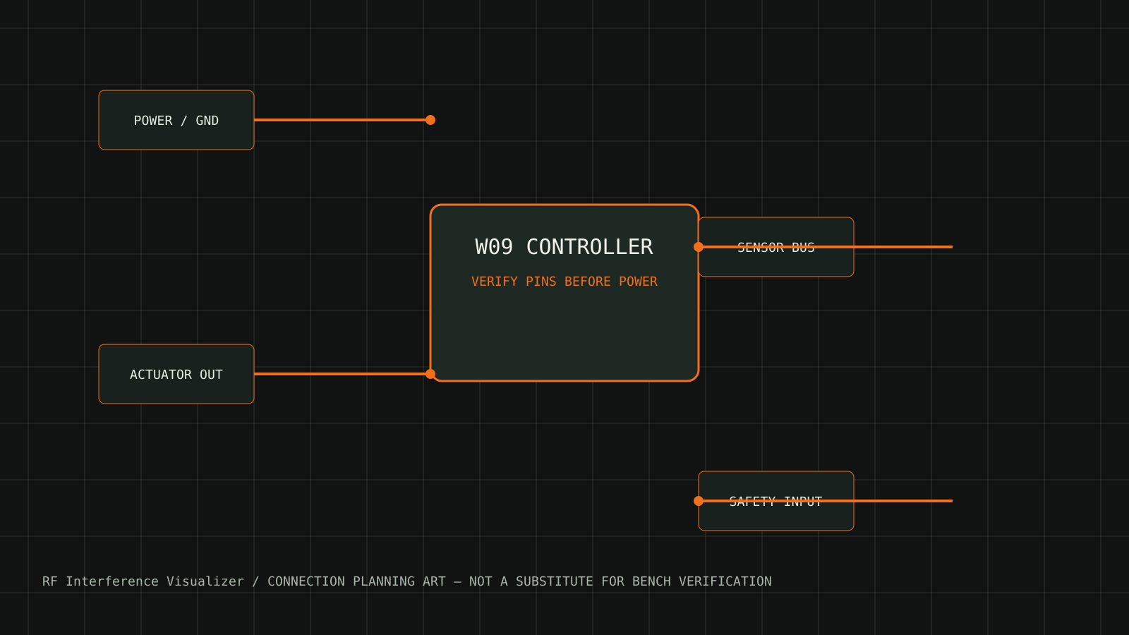
- Inventory the board, actuators, sensors, and power rails listed for W09.
- Build and inspect the low-voltage wiring against the supplied connection diagram before connecting actuators.
- Flash the firmware, run the startup self-check, and record the printed board and firmware version.
- Calibrate the sensors and limits, then run the acceptance tests at the lowest safe energy level.
Test and expected result
Use shielded or controlled test sources, validate frequency scale, and avoid transmission.
Safety and limits
No jamming, spoofing, interference, or unauthorized capture.
Download connection diagram SVG