Wireless Auditing & RF Projects · Intermediate
nRF24 Packet Link Tester
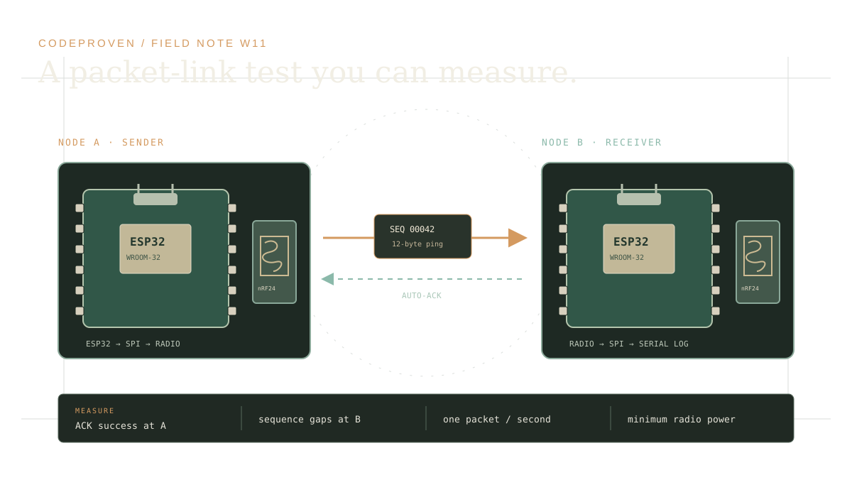
Measure acknowledged packet delivery between two ESP32 boards and nRF24L01+ modules you own. A pair of user-owned ESP32 and nRF24L01+ nodes measures one short acknowledged test packet per second and reports delivery and sequence gaps over USB serial.
Components
- 2 × ESP32-WROOM-32 development boards
- 2 × standard nRF24L01+ modules without PA/LNA
- 2 × 100 µF electrolytic capacitors rated at least 6.3 V, one per radio
- 2 × 0.1 µF ceramic bypass capacitors, one per radio
- Jumper wires and 2 USB data cables
- Two computers or two serial-monitor windows for comparing logs
Build steps
- Wire each ESP32 to its own nRF24L01+ using the supplied diagram. Use 3.3 V only at the radio VCC pin; place both capacitors directly across each radio's 3.3 V and GND rails with electrolytic polarity checked.
- Install the RF24 library by TMRh20. Open W11_nrf24_packet_link_tester.ino and set LINK_NODE to 0 for the sender board; compile and upload it.
- Change LINK_NODE to 1, then compile and upload the same sketch to the receiver board. Do not power the radio from the ESP32 5 V pin.
- Place the boards on a nonconductive bench about one metre apart. Open both Serial Monitors at 115200 baud and keep the default fixed channel and minimum transmit-power setting.
- Compare sender acknowledgement results with receiver sequence numbers for at least 60 seconds. Change only one link condition at a time and record what changed.
Test and expected result
The sender reports whether each packet received the radio's automatic acknowledgement. The receiver prints each valid sequence number and counts gaps. A nearby, clear bench link should usually show increasing sequence numbers and mostly successful acknowledgements; actual range and packet loss depend on modules, supply decoupling, antenna, and local RF conditions.
Safety and limits
For a controlled test between your own paired nodes only. The sketch uses a fixed channel, minimum nRF24 transmit-power setting, and one short packet per second; it contains no carrier mode, noise generation, channel sweep, or interference feature. Check local radio rules and board pin limits. Never connect nRF24 VCC to 5 V. This educational sketch and diagram are not hardware-certified; inspect wiring and module supply requirements before power-up.
Terms, safety and privacy
For paired devices you own or are authorized to operate. The sketch sends one short test packet per second at minimum power. It does not scan or disrupt other devices. The project page requires acknowledgment before enabling downloads. The acknowledgment flag stays in this browser.
Open the interactive project page and acknowledge its safety notice to enable the firmware and wiring downloads.