ESP32 & ESP8266 Connectivity · Beginner · Web control
ESP32 Web Relay Controller
Two relays and a page that switches them, served by the board itself with no cloud in the middle.
Firmware status: Generated from this project's own pin map and compiled with arduino-cli for esp32:esp32:esp32 before publication; bench validation on your hardware is still required.
Board: ESP32 DevKit (ESP32-WROOM-32, 30 or 38 pin) · ESP32 dual core @ 240 MHz · 3.3 V logic · build for esp32:esp32:esp32.
What you will build
An ESP32 serving a control page that switches two relay channels and reads two inputs, with everything on your own network.
Components
- ESP32 board
- 2-channel relay module (opto-isolated, 5 V coil)
- 2 × 10 kΩ pull-down resistors for the inputs
- USB cable
- 5 V supply sized for the relay coils
Pin map for this build
| Sketch constant | Pin | What it is |
|---|---|---|
PIN_OUT_1 | 4 | Switched output — relay / MOSFET channel, 5 V coil |
PIN_OUT_2 | 5 | Switched output — relay / MOSFET channel, 5 V coil |
PIN_IN_1 | 34 | Analog input — 3.3 V maximum at the pin |
PIN_IN_2 | 35 | Analog input — 3.3 V maximum at the pin |
Tools
- USB programming cable
- Multimeter
- Current-limited bench supply (for anything that switches a load)
- Small screwdriver and wire cutters
Build sequence
- Wire the relay inputs to two GPIO and its supply to 5 V, keeping the board's ground and the relay ground common.
- Wire the two sense inputs through 10 kΩ pull-downs so a disconnected wire reads low, not floating.
- Flash, open the printed address, and switch each channel while watching the relay's LED and listening for the click.
- Read /data to confirm the JSON shape your own code will consume.
Test and expected result
Each channel clicks and its indicator follows the page, inputs report in the JSON, and the board survives a power cycle with the relay states it started in.
Acceptance checks
both channels switch, inputs readable, page works from a phone
Safety and limits
A relay can switch mains, and this guide does not: keep the switched load low-voltage. Mains wiring needs enclosure, isolation and a qualified check.
Hardware scope
Two digital outputs through a relay module, two analog inputs, HTTP control page.
Connection diagram
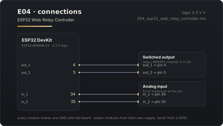
Download the connection diagram (SVG)
Download the Arduino sketch (E04_esp32_web_relay_controller.ino)
Guide source: the sketch on this page was generated from the pin map above and compiled for esp32:esp32:esp32 before publication.
Related projects
- ESP32 Captive Portal Wi-Fi Manager — Boot the ESP32 with no credentials and configure its network from a phone, with the portal saved to flash.
- ESP8266 Config Portal — The same idea on the cheapest board that can do it: an ESP8266 that configures itself from a browser.
- ESP8266 Sensor Portal Logger — A battery-minded sensor node you configure in the field, with the reading shown on its own setup page.